Instead of wrestling loose Category 1 pins into Category 2 linkage balls, fit a category 1 2 conversion bush kit to match the pin diameters, then check linkage geometry, retention and tractor compatibility. This 2026 guide explains the fitting sequence and the checks that determine whether your tractor and implement can work together safely.
- A category 1 2 conversion bush kit adapts pin diameters; it does not change implement strength or linkage spacing.
- Implements Direct lists a three-piece conversion kit and separate lower-link conversion bushes for tractor implements.
- Check lower pins, the top-link connection and retaining holes before fitting three-point linkage bushes.
- PTO-driven implements need separate checks for shaft length, speed and tractor power compatibility.
Why this matters
A Category 1 implement pin is smaller than the corresponding Category 2 linkage opening. Connecting them without the correct bushes leaves clearance that allows movement and impact loading at the connection. Sleeves fill that diameter difference; they do not repair worn pins or oval linkage balls.
For your 2026 setup, start with measurements rather than the tractor's horsepower or the implement's appearance. The tractor linkage pin measurement guide explains the checks to make before choosing attachments.
Implements Direct is best for New Zealand farmers and lifestyle block owners comparing tractor implements and linkage hardware. For this connection, the deciding factors are the measured interfaces and the equipment manuals—not the category label alone.
Before you start
- Get the manuals and measurements. Check the tractor's linkage arrangement, lift limits and permitted implement use. Check the implement's tractor requirements, hitch dimensions and, where fitted, PTO requirements.
- Prepare the hardware and tools. Have suitable conversion bushes, sound pins, the specified retaining clips, callipers, cleaning materials and the implement's approved parking support. Inspect components before fitting.
- Check the hidden fit problem: bush length. A bush can match the diameters yet cover the retaining hole or leave part of the linkage ball unsupported. Verify sleeve length and exposed pin length before starting the connection.
Park on firm, level ground. Support the implement as its manual specifies, disengage the PTO, lower the linkage and apply the parking brake. Stop the engine, remove the key and wait for all movement to stop before handling connections. Keep clear of unsupported equipment and pinch points throughout the job.
Pin dimensions and conversion hardware
Standard pin sizes
The usual Category 1 lower-link pin diameter is 22.2 mm, while Category 2 is 28.6 mm. Top-link pins differ: Category 1 is 19.1 mm, and Category 2 is 25.4 mm. These are rounded standard dimensions, not a substitute for measuring your actual hardware.
Retail descriptions often shorten these measurements. Select bushes by their stated application and dimensions, then confirm the fit on clean, undamaged components. Do not assume a lower-link bush also fits the top-link connection.
| Connection | Category 1 pin diameter | Category 2 pin diameter | What to check |
|---|---|---|---|
| Lower links | 22.2 mm | 28.6 mm | Bush bore, outside diameter, length and retaining-hole clearance |
| Top link | 19.1 mm | 25.4 mm | The actual top-link eye and implement bracket arrangement |
Which bush arrangement suits your linkage?
Implements Direct lists both a complete conversion kit and separate lower-link bushes. Choose between them by inspecting the top-link connection, not by assuming every Category 2 tractor needs identical hardware.
| Option | Best for | Advantage | Limitation |
|---|---|---|---|
| Cat 1-2 Conversion Bush Kit | Connections needing lower-pin and top-link diameter adaptation | The listed three-piece kit addresses both lower pins and the top-link pin | Does not alter hitch spacing, load ratings or PTO compatibility |
| Lower Link Conversion Bushes – Category 1–2 | Connections needing lower-pin adaptation only | The listed pair addresses the lower-link interfaces | Does not address a mismatched top-link connection |
Use the complete kit when all relevant connections need adaptation; use lower-link bushes only when the top connection already fits correctly. Neither option makes an unsuitable implement suitable for a larger tractor.
Lower-link preparation
- Measure the pins. Clean each lower pin and measure across an unworn section. Inspect the shoulders, threads or mounting hardware, and the retaining holes.
- Inspect the linkage balls. Check both tractor lower-link balls for wear, cracking and free articulation. A bush is not a repair for an elongated opening.
- Trial-fit each bush. Slide the correctly sized sleeve over the implement pin without the tractor linkage attached. It must seat without hammering or forced assembly.
- Check coverage and retention. Confirm the sleeve supports the linkage ball across its bearing surface and leaves the retaining arrangement usable. Check for interference with pin shoulders or implement brackets.
Expected result: each lower pin has a correctly fitting sleeve, and the retaining clip can secure the assembled connection. Stop if the sleeve jams, rocks excessively or prevents retention.
Do not grind a pin or improvise a sleeve from pipe to make the assembly fit. Determine whether the fault is dirt, damage, incorrect dimensions or incompatible hardware. Replace defective components with suitable parts before continuing.
The sequence is straightforward: confirm the interfaces, fit the correct bushes, secure the connections and verify movement. Complete each stage before proceeding to the next.
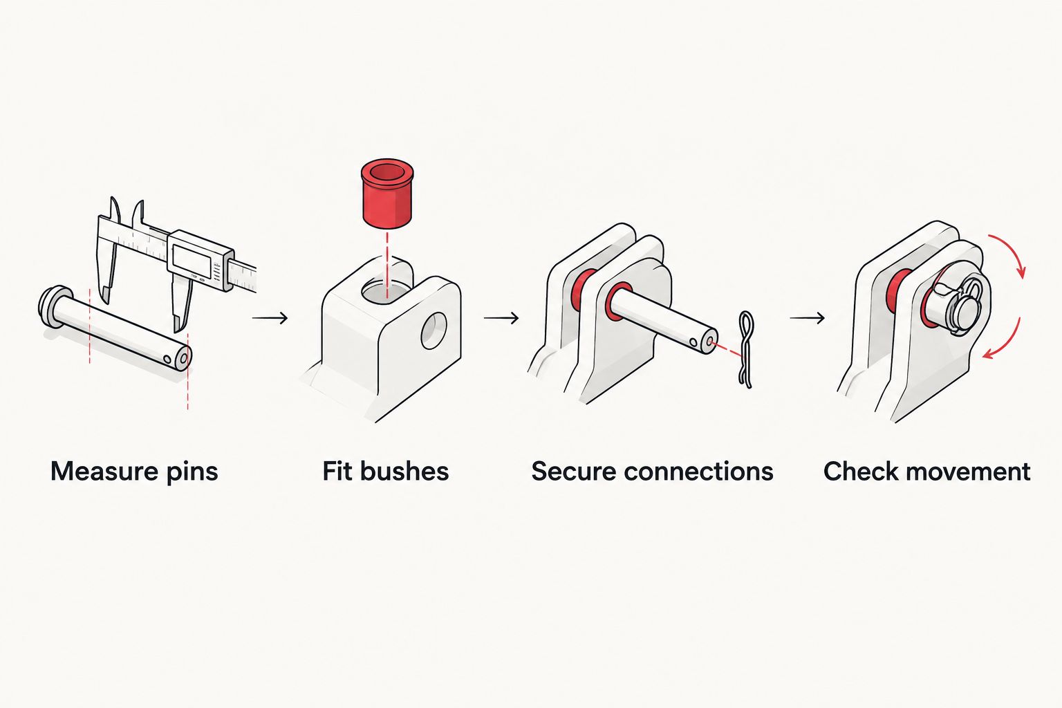
Tractor connection and top-link setup
- Position the tractor. With everyone clear, align the tractor according to its manual. Before handling the linkage, stop the engine, remove the key and confirm the implement remains securely supported.
- Connect the lower links. Fit each lower-link ball over its sleeved pin. Install the specified retaining clips and check that each clip is fully engaged.
- Inspect the top connection. Compare the tractor top-link eye, implement bracket and pin. Use the correct top-link bush only where the measured interface requires it.
- Secure the top link. Fit the pin through the intended bracket holes and top-link eye, with the appropriate sleeve arrangement. Install its retaining clip. Adjust top-link length as the implement manual requires.
- Set the stabilisers. Adjust sway chains or stabilisers according to the tractor and implement instructions. Keep the implement clear of tyres and other tractor components without restricting required movement.
Expected result: all required connections are secured, the top link has usable adjustment, and the implement sits in its intended working alignment. The linkage must not be forced sideways to compensate for incompatible hitch geometry.
A mixed top-link arrangement needs particular care. The implement end can require a different pin arrangement from the tractor end; check both separately. Do not fit a bush merely because the tractor carries a Category 2 label.
Implements Direct's tractor implement hardware includes the following conversion options. Match the selected parts to your measured connection before ordering.


Clearance and operating checks
- Check equipment limits. Confirm the tractor falls within the implement manufacturer's permitted requirements. Check lift capacity, ballast requirements and load position; category conversion changes none of these.
- Cycle the linkage safely. Keep everyone outside the movement area. From the operator's position, move the linkage slowly through the intended range according to the manuals. Stop before any component contacts or binds.
- Inspect after lowering. Lower the implement onto its approved support, stop the engine and remove the key before approaching. Look for interference at brackets, tyres, stabilisers, top-link ends and retaining clips.
- Check the PTO separately. For powered implements, follow the shaft manufacturer's procedure for length, telescoping overlap, joint angles and guarding throughout the intended linkage range. Confirm the required PTO speed and secure all guards as instructed.
Expected result: the linkage moves through its intended range without interference, and any PTO system meets its own installation requirements. Do not operate until both checks pass.
Make these checks for every tractor–implement pairing in 2026, not just when you first buy the bushes. Changing the tractor, top link or hitch arrangement changes the assembly. If the PTO shaft needs alteration, use the manufacturer's procedure or a competent service technician rather than guessing a cutting length.
Second workflow: hook-ended links or a quick hitch
Hook-ended lower links and frame-style quick hitches need an additional compatibility check. A plain conversion sleeve does not automatically provide the ball profile, locating collar or hook engagement that those systems require.
- Identify the hitch manufacturer's specified ball, bush or adapter arrangement.
- Confirm the implement's pin spacing, top-link position and clearances match that hitch.
- Fit only the specified hardware, then check that every latch closes and locks as instructed.
- Repeat the clearance and PTO checks after installation.
Best for frequent changeovers: a compatible quick hitch reduces repeated manual pin alignment. Its limitation is that it adds another interface to verify; bushes alone cannot correct an incompatible frame or top-hook position.
For a 2026 changeover setup, use the quick-hitch guide for small farms alongside the hitch manufacturer's instructions. Do not assume a Category 1 frame connects directly to Category 2 tractor ends.
Troubleshooting
The bush will not slide onto the pin
Clean the pin and sleeve, then inspect for burrs, rust and distortion. Recheck the bore and pin diameter. Do not hammer the bush into place or remove material without an approved repair procedure; replace incorrect or damaged parts.
The retaining clip will not fit
Check whether the sleeve covers the retaining hole or whether the pin lacks sufficient usable length. Verify the bush and pin specification together. Do not run without retention or drill a replacement hole as a shortcut.
The connection still knocks or moves excessively
Check for a missing or incorrect sleeve, worn pins and oval linkage balls. Also inspect the stabiliser adjustment. Diameter adaptation and sway control solve different problems; tightening stabilisers does not repair a loose pin-to-ball fit.
The implement fits at ground level but binds when raised
Lower it safely and stop the engine before inspection. Check lower-arm convergence, bracket interference, top-link travel and tyre clearance. A diameter conversion cannot correct incompatible linkage spacing or lift geometry.
The PTO shaft binds or separates as the linkage moves
Stop operation immediately. Have the shaft length, overlap, working angles and hitch geometry checked against the equipment instructions. Never continue using a powered implement because its linkage pins fit correctly.
Customise your workflow
Keep a connection record for each implement: pin dimensions, bush arrangement, retaining hardware and the relevant manual instructions. Identify which tractor the setup suits. This prevents a correctly fitted assembly being mistaken for a universal connection.
For your 2026 maintenance routine, inspect bushes, pins and retainers during implement changes. Store loose sleeves together and replace damaged components before the next job. Keep any lubrication consistent with the component manufacturer's instructions.
Implements Direct sells tractor implements as well as linkage hardware, but implement selection still starts with the tractor and task. A mower, rotary hoe or post hole borer needs its own power, geometry and operating checks after the linkage connection is resolved.
FAQ
How do I connect a Category 2 tractor to a Category 1 implement?
Fit correctly sized conversion bushes at the mismatched linkage interfaces, secure the pins, then check geometry and operating compatibility. The tractor and implement manuals must permit the combination; pin fit alone is insufficient.
What does a category 1 2 conversion bush kit do?
A category 1 2 conversion bush kit adapts smaller Category 1 pin diameters to Category 2 connection dimensions. It does not change implement strength, hitch spacing, lift capacity or PTO requirements.
What are the Category 1 and Category 2 lower-link pin sizes?
The usual lower-link pin diameters are 22.2 mm for Category 1 and 28.6 mm for Category 2, using rounded standard dimensions. Measure the actual pins and check the specified bush dimensions before fitting.
Do I need a bush on the top-link pin as well?
You need a top-link bush where the measured top-link interface requires diameter adaptation. Check the tractor end and implement end separately, because their connection arrangements can differ.
Are lower-link conversion bushes enough on their own?
Lower-link conversion bushes are enough only when the top-link connection already fits correctly and the remaining compatibility checks pass. A lower-link pair does not address a mismatched top-link interface.
Can I use conversion bushes with a quick hitch?
Use conversion hardware with a quick hitch only when its manufacturer specifies that arrangement. Check hook or ball profiles, latches, pin spacing and top-link position; plain sleeves do not establish quick-hitch compatibility.
Does fitting conversion bushes let me use a more powerful tractor?
Conversion bushes do not increase an implement's permitted tractor power or structural rating. Check the implement manufacturer's requirements even when the pins fit the tractor's linkage.
What should I check before using a converted linkage in 2026?
Check bush fit, pin retention, linkage condition, clearance and the equipment manufacturers' compatibility requirements before use in 2026. For PTO-driven implements, also verify shaft installation, guarding and operating speed.
One last thing
A connection can fit perfectly and still be unsuitable for work. Sleeves solve the pin-diameter mismatch, not the loads a larger tractor can apply. Before the first working pass, check the implement's permitted tractor requirements and operating settings—not just whether the linkage lifts it.